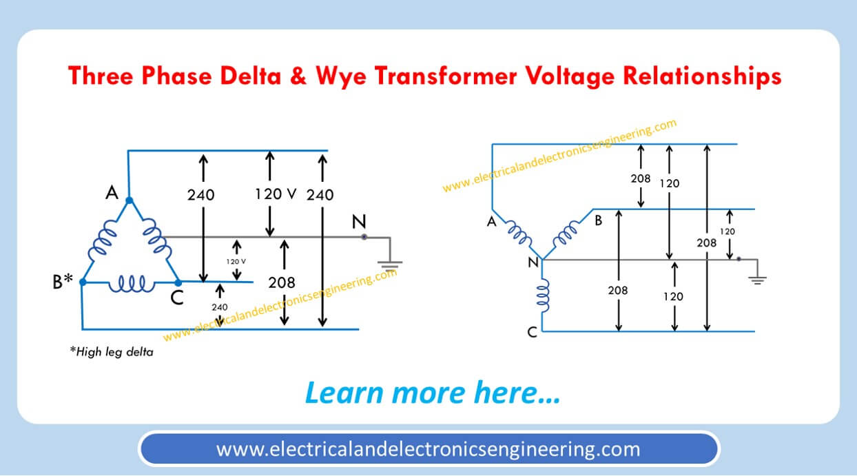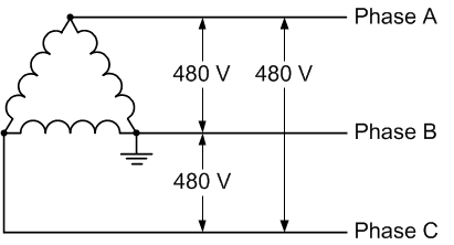

The two center tapped voltages are also hot to ground. The secondary on the left is connected hot to ground, and the one on the right is connected hot to hot. Both primary and secondary coils have two. What stands out in Figure 1 is that only two connections are at any point on the schematics. The turns ratio determines the increase or decrease in voltage and current between the primary and secondary coils.

If it did, more would be in the primary than in the secondary since both are reducing the primary voltage. Note that these illustrations do not show any difference in the number of primary and secondary turns. It also has a grounded, neutral center tap that produces 120 volts between the tap and the outside terminals. The schematic on the right takes that same primary voltage and produces 240 volts.

The one on the left takes a higher primary voltage and produces 120 volts in the secondary. The two typical single-phase transformer schematics Figure 1 shows the schematics for two typical single-phase transformers.įigure 1. Single-Phase Wye Connection and Delta ConnectionĪ simple illustration of why a Wye or Delta connection is required in a three-phase circuit is to look at a single-phase connection.


 0 kommentar(er)
